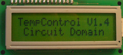
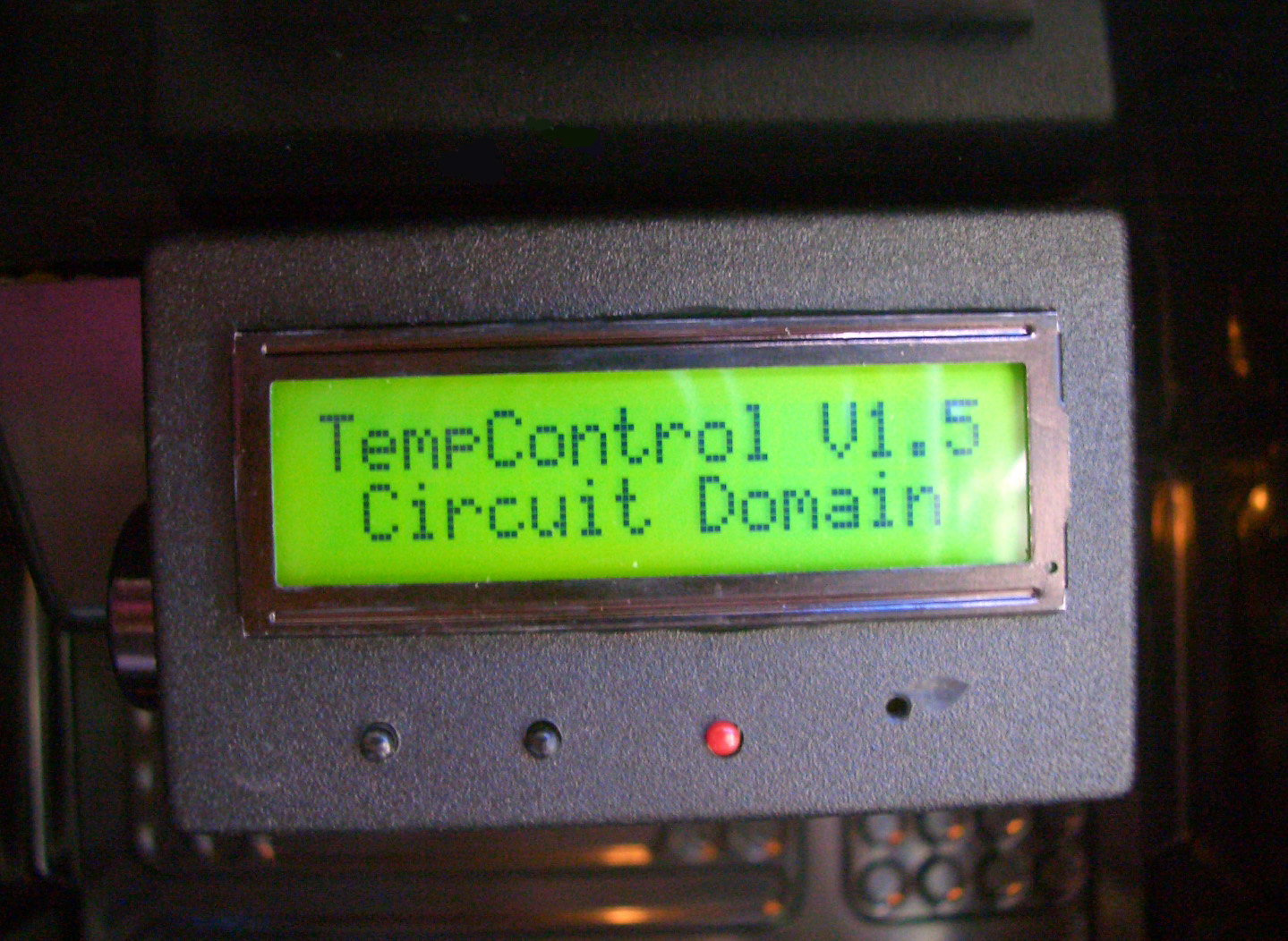
Universal Temperature Controller
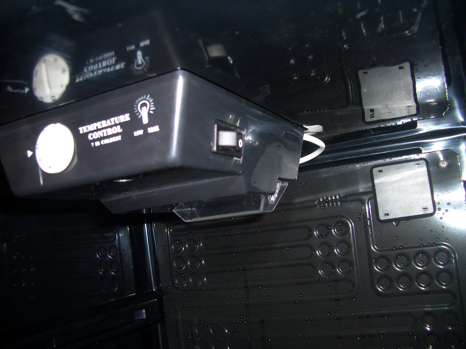
I have recently purchased a cooler for my pool room. However after turning it on I was disappointed to find out that it didn't cool the beer enough, the temperature was around 12°C. Naturally I didn't want to take it back as this was the last display model and it blends in with my pool room décor very well, so I took it apart and started adjusting the mechanical thermostat hoping to bring the average temperature down by few degrees. I have finally arrived at the correct temperature of 6°C. Due to usage of mechanical thermostat the temperature varies quite a lot, from 5°C to 14°C. Especially when we play pool and have a few. The door is opened every 10-15 minutes. The cooler is not large so it only takes a second or two to let all the cold air out. When this happens the thermostat does not react as the temperature it measures is off the back cooling plate which is still very cold. This is unacceptable as the beer gets warm very soon. This coupled with a manualy controlled light and lack of alert when the door is not closed correctly had prompted me to design a digital temperature controller. This is where the fun starts.
I decided to base this project on PIC16F88 microcontroller as it is common, cheap, has enough I/O lines for the design and has an inbuilt A/D converter. To complement the MCU I have also chosen LM335Z Precision Temperature sensor for two main reasons, it produces a linear output which is proportional to temperature. Both of these components are readily and cheaply available from any Jaycar or Dick Smith Electronics store.
The project had to comply with few pre-requisites that I have drawn up from the (for the lack of better words) cheap and dysfunctional design of the wine cooler controller. These are:
2. Has to be fully programmable, Min, Max, Timeouts etc.
3. Has to control the interior light with programmable timeout.
4. Has to alert if door is not closed properly by a series of annoying beeps.
5. Has to be simple in design.
6. Can be used to control a cooler or heater (set through a menu).
7. Must include ICSP (In Circuit Serial Programming). This means the controller can be re-programmed after installation.
Proof of concept
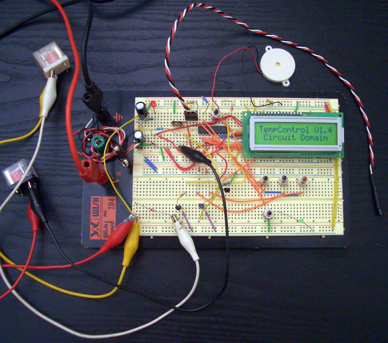
The design proof of concept is a very important step of device development. It allows testing and perfecting the functionality of every little block of circuit as well as gives an oportunity to write and test the initial code for the microcontroller. I always use vero board to test and add to the design. It is very easy to validate and modify a working circuit. You can add and alter different circuit segments to make sure they will perform as designed as well as work together to form a final design. Any succesive changes made on the vero board are transfered to the schematic diagram. It is also very handy to keep track of changes made in a simple text file called Release.txt for future reference.
Schematic Diagram
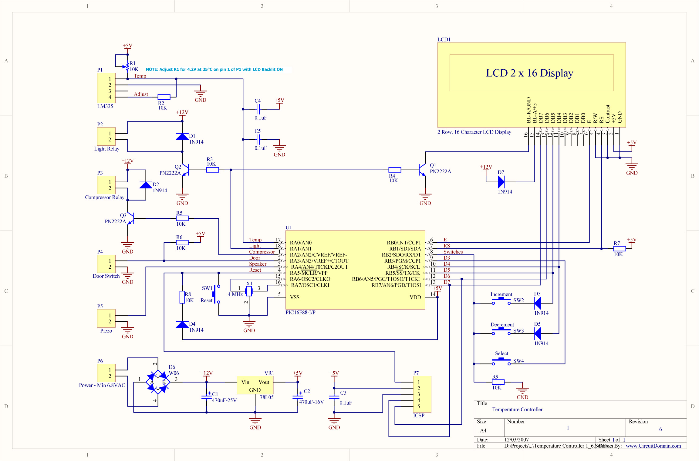
The circuit schematic is very simple and involves couple of tricks to control all the devices and sensors. PortB I/O lines are shared between LCD, buttons and ICSP. This project is my first to involve ICSP and I tell you it works a treat!!! I can't believe I haven't done this earlier. I found all the necessary information on ICSP on this great page www.instructables.com With minor modifications of my PIC Programmer I can now flash new firmware to installed circuits in a matter of seconds. This saves lots of time not to mention wear and tear on the PIC microchip by eliminating removal from the circuit for programming, this makes debugging code that much quicker. The circuit uses common components and is so simple in design that I really have nothing more to say about it.
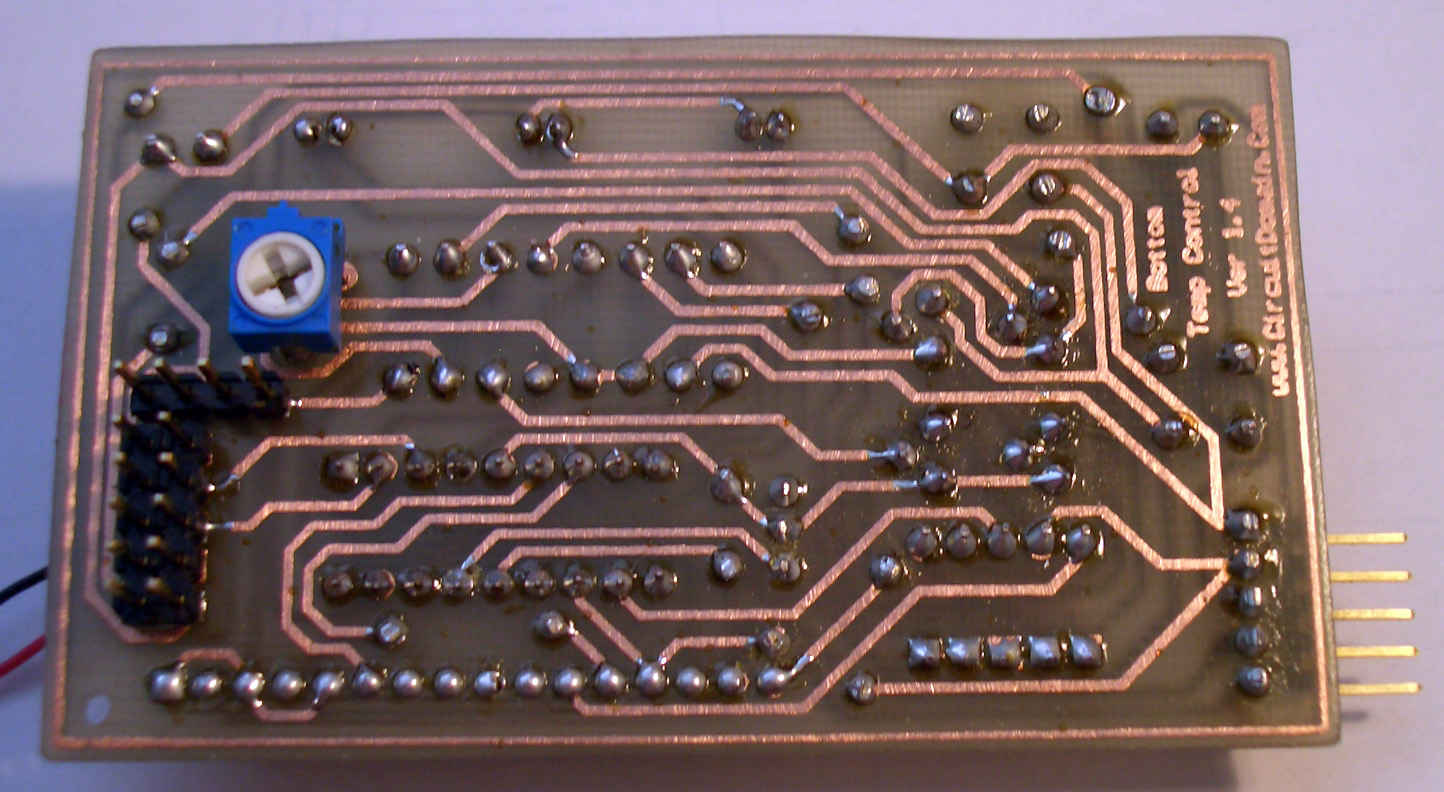
Circuit Board
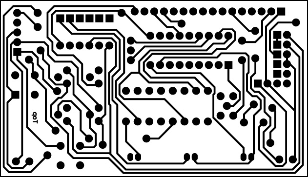
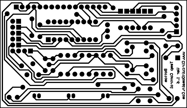
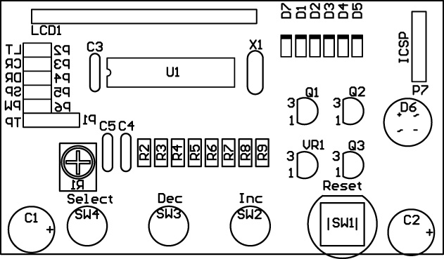
The circuit board is double sided, and not too difficult to manufacture if you follow the few easy steps on my PCB Prototyping page. There are few things to keep in mind when soldering the components on to the PCB. If you follow the few below steps you should have no problems:
1. Solder in the via's first making sure they do not protrude too high, especially around C1 as the cap will be mounted horizontally.
2. Solder in the small components first (resistors, small caps and diodes) making sure you solder both sides of the PCB on pins that have tracks on Top layer. Check your work.
3. Solder in the pin headers and bigger components ( transistors and switches) as per step 2 keeping in mind that R1 and P1-6 are soldered on the bottom side of the PCB.
4. Solder in the remaining components leaving the microcontroller U1 and LCD last. Check your work.
5. Power up the circuit and check for +5V on Pin 14 of U1 and Pin 2 of LCD header.
6. Solder in the microcontroller U1.
7. Set R1 mid way.
The PCB should look like the bellow pictures.
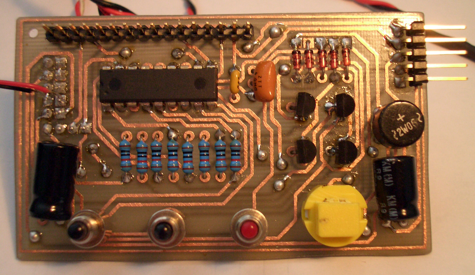
7. When you are satisfied with the job so far then solder in the LCD display to LCD header.
Microcontroller Firmware
The firmware is the brains of the circuit, it controlls all the functions and programmable options. Bellow is an explanation of all the programmable features included for this project.
1. Main Display screen.

Main display screen is where the controller will spend most of it's time. It displays the current temperature reading from the sensor as well as displaying current state (Active/Not Active) of the compressor relay by the means of a spinner icon on the bottom right. This screen is the default and will be returned to from any menu after 5 second inactivity. Using "Select" button will togle through the different menu screens. The software does not support negative temperature so it will also limit the temperature reading to 0ºC.
2. Minimum Temperature Display screen.
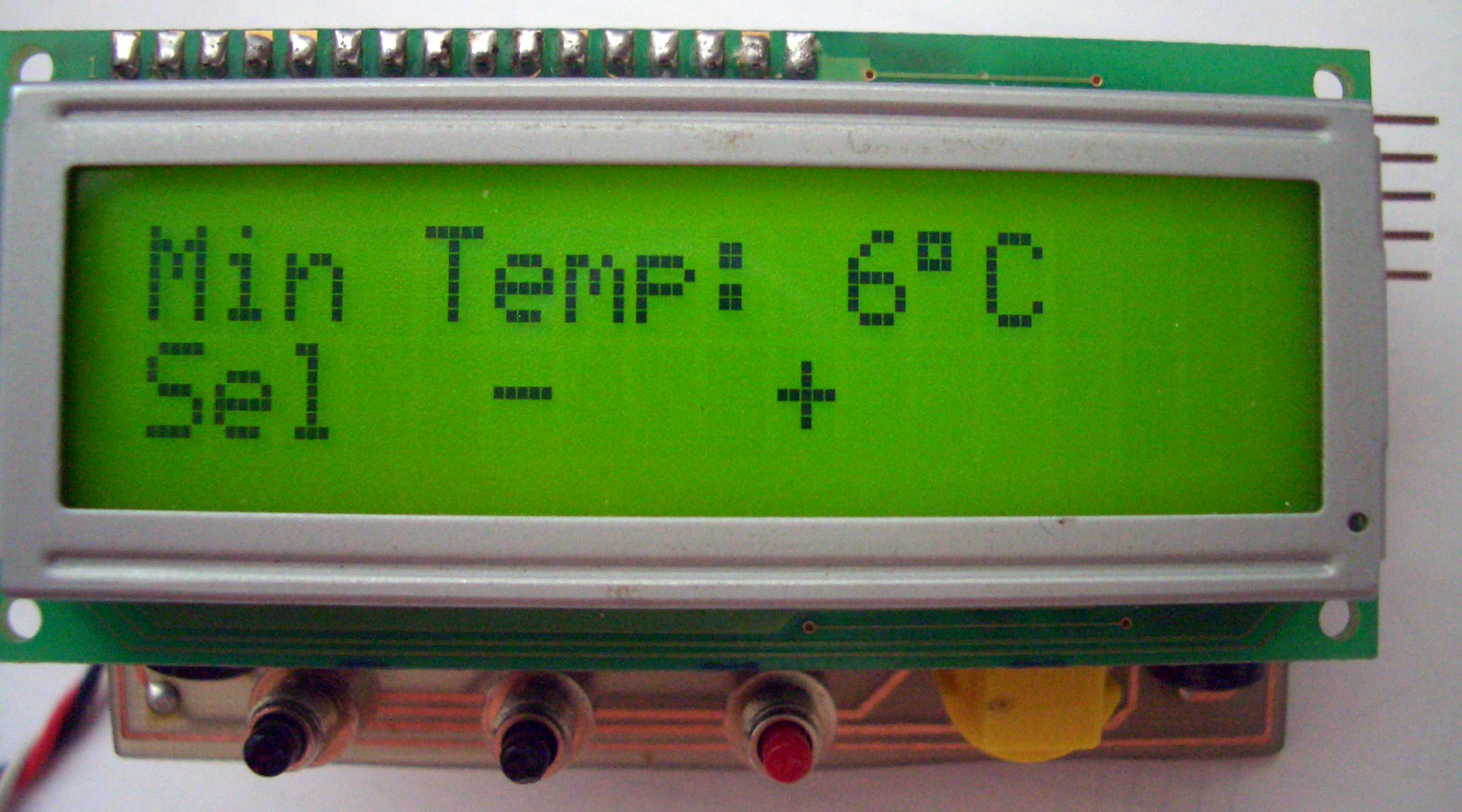
On this screen you can adjust the minimum temperature trigger for the compressor relay. In "Cooler" mode this value once reached on the Main Display will turn off the compressor as the minimum temperature had been reached. In "Heater" mode this value once reached on the Main Display will turn on the heater as the minimum temperature had been reached. Use "+" or "-" buttons to set the correct minimum temperature. As the minimum temperature can not equal or be higher than maximum temperature the software will adjust the maximum temperature to account for this. The software does not support negative temperature so it will also limit the value to 0ºC.
3. Maximum Temperature Display screen.
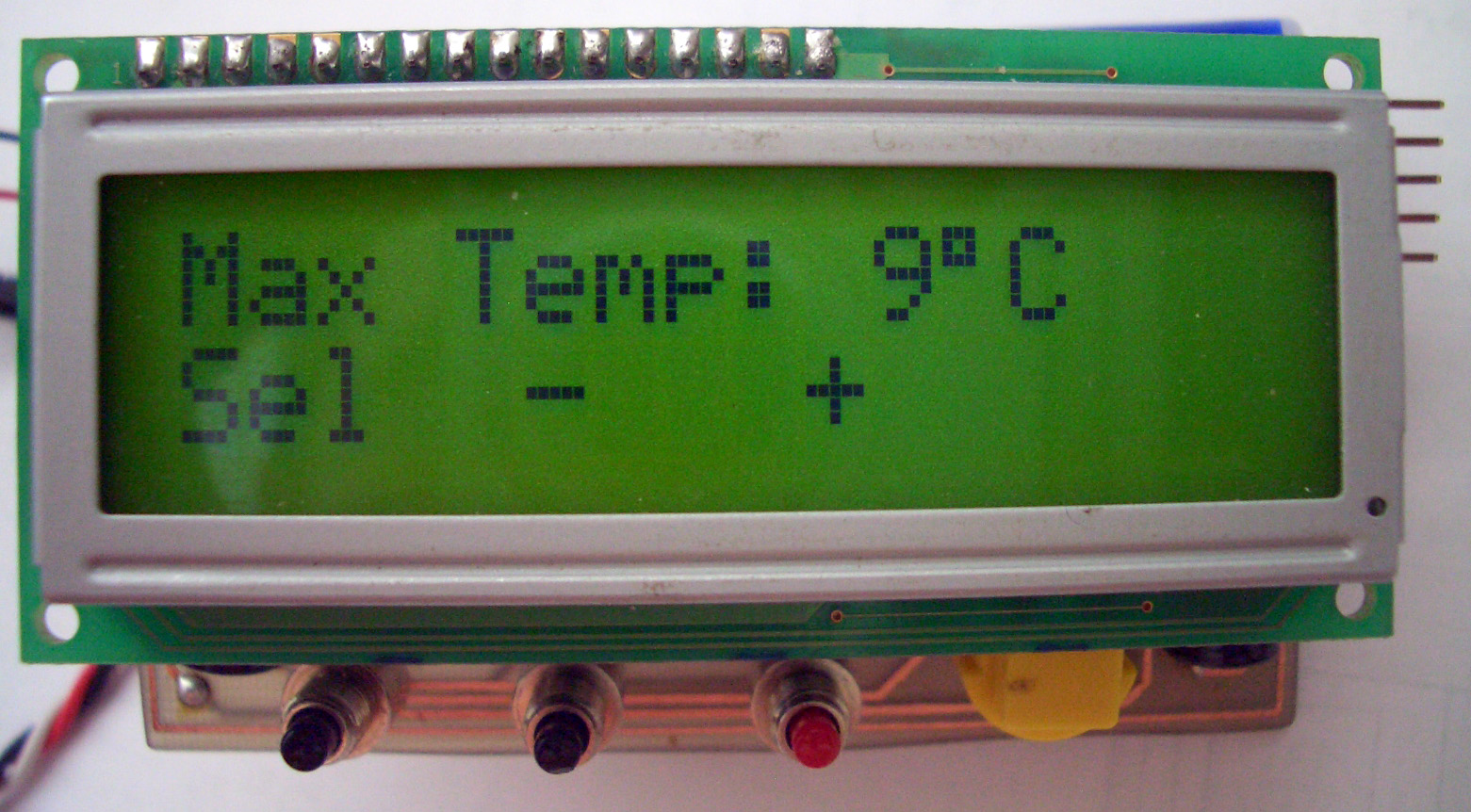
On this screen you can adjust the maximum temperature trigger for the compressor relay. In "Cooler" mode this value once reached on the Main Display will turn on the compressor as the maximum temperature had been reached. In "Heater" mode this value once reached on the Main Display will turn off the heater as the maximum temperature had been reached. Use "+" or "-" buttons to set the correct maximum temperature. As the maximum temperature can not equal or be lower than minimum temperature the software will adjust the minimum temperature to account for this.
4. Calibration screen.
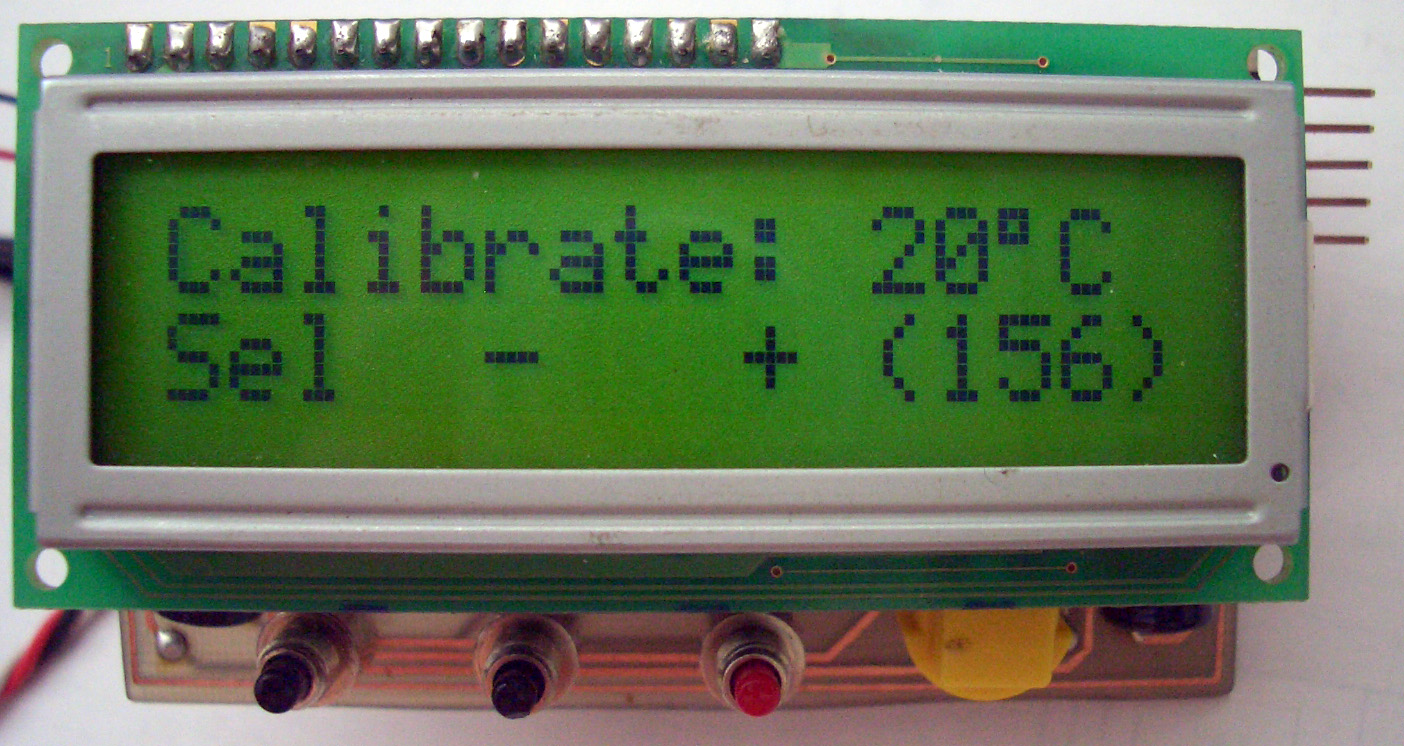
The controller has been designed to compensate for the temperature sensor physical placement in the fridge. This functionality is a requirement as the temperature is not constant through the interior of the fridge. As you know warm air rises, or in this example cold air sinks to the bottom of the fridge. This means that temperature at the bottom of the fridge will be few degrees lower than the temperature at the top (this is where the sensor resides in this project). To compensate for the temperature difference you can use this screen and manually adjust the offset needed. You need to use a commercial digital unit to tell you the actual temperature in the middle of the fridge and adjust the readout on the Universal Temperature Controller using the "+" or "-" buttons to display the correct Temperature. Simple as !!!
5. Door Timeout screen.
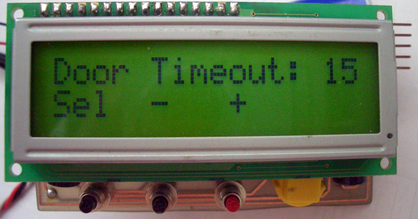
On this screen you can adjust the time (in seconds) after which the controller sounds continuous beeps to let you know the door is not closed correctly. When the time is reached the interior light and LCD backlit are also disabled as the controller assumes the door is not closed correctly. This time is counted down from the point after the door has been opened. Use "+" or "-" buttons to set the correct timeout. A value of 0 will disable the beeps. Maximum allowable value is 99 seconds. This value is adjustable, however only takes effect in "Cooler" mode. In "Heater" mode the door switch and warning beeps are disabled.
6. Light Timeout screen.
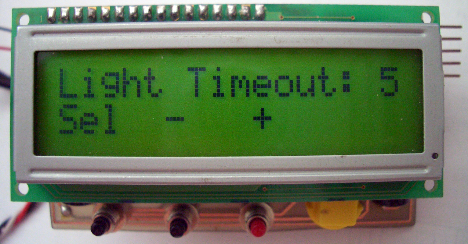
On this screen you can adjust the time (in seconds) after which the controller turns off the interior light. This time is counted down from the point after the door has been closed. Use "+" or "-" buttons to set the correct timeout. A value of 0 will turn the light off immediately when the door is closed. Maximum value is 10 seconds. This value is adjustable, however only takes effect in "Cooler" mode. In "Heater" mode the light output and LCD backlit are always on.
7. Operational Mode screen.
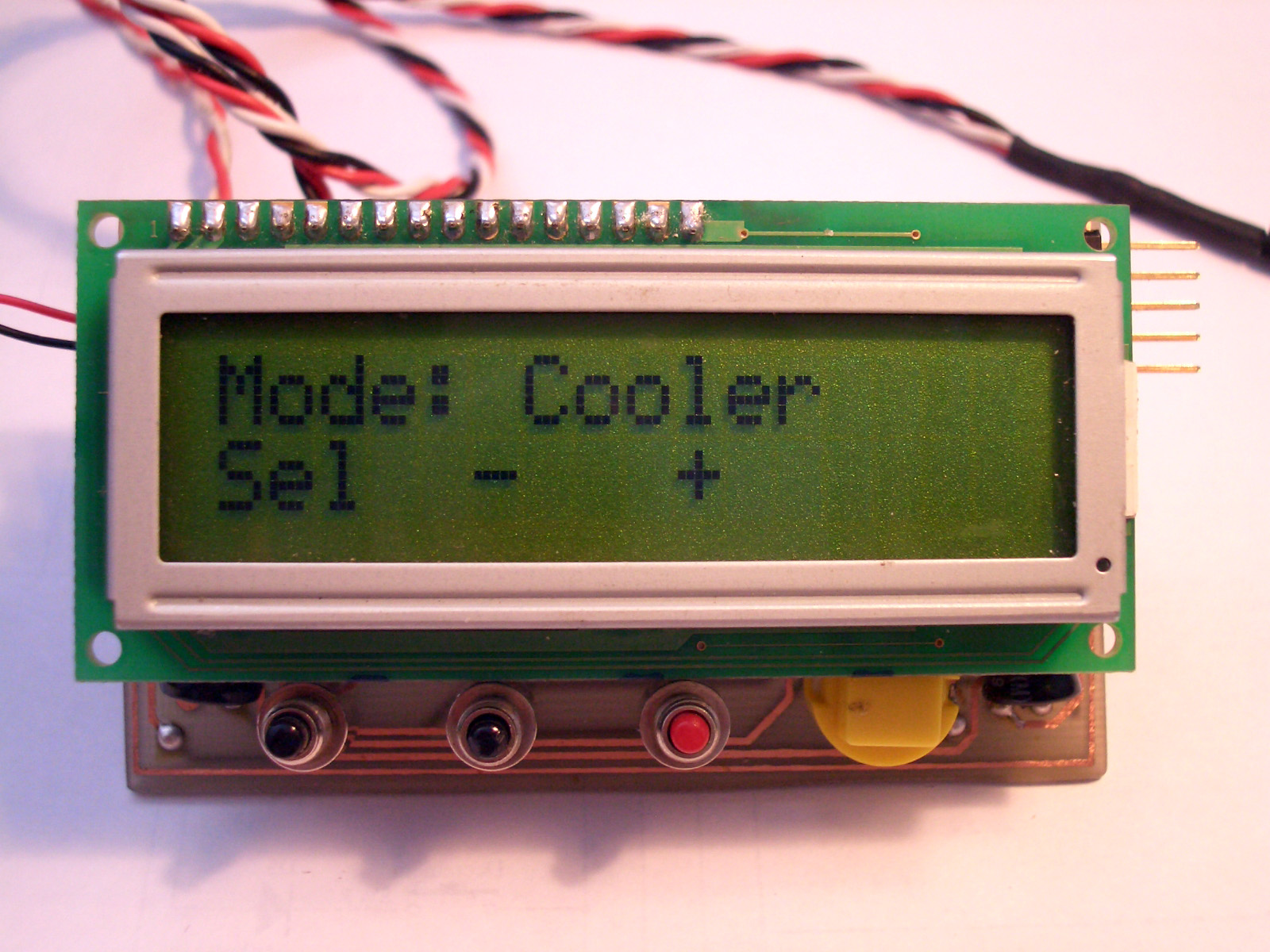
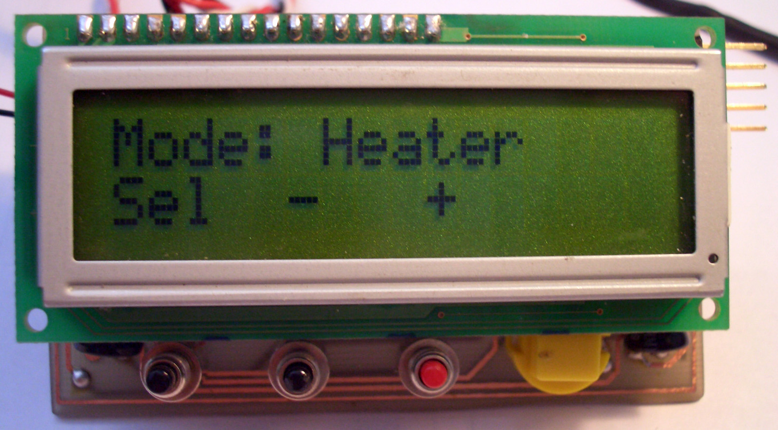
On this screen you can set the mode in which the controller will operate. Setting this mode will change the compressor/heater relay operation. Use "+" or "-" buttons to toggle the mode.
Now that you had a chance to fully examine the software functions and the over all design features I am sure you are asking yourself "Where can I download the firmware for the microcontroller?". The Demo firmware is available here. It is fully functional with the exception of actually controlling the compressor/heater relay. You can download it and evaluate it. If you are impressed with the design of this project and want to use it to controll a fridge or a heater then you can download full release firmware from Circuit Domain Shop. If you have already purchased Universal Temperature Controller firmware and want to upgrade it to current version, please use the same form to submit your request. Firmware upgrades are FREE, provided you have previously purchased the firmware and your hardware version is supported.
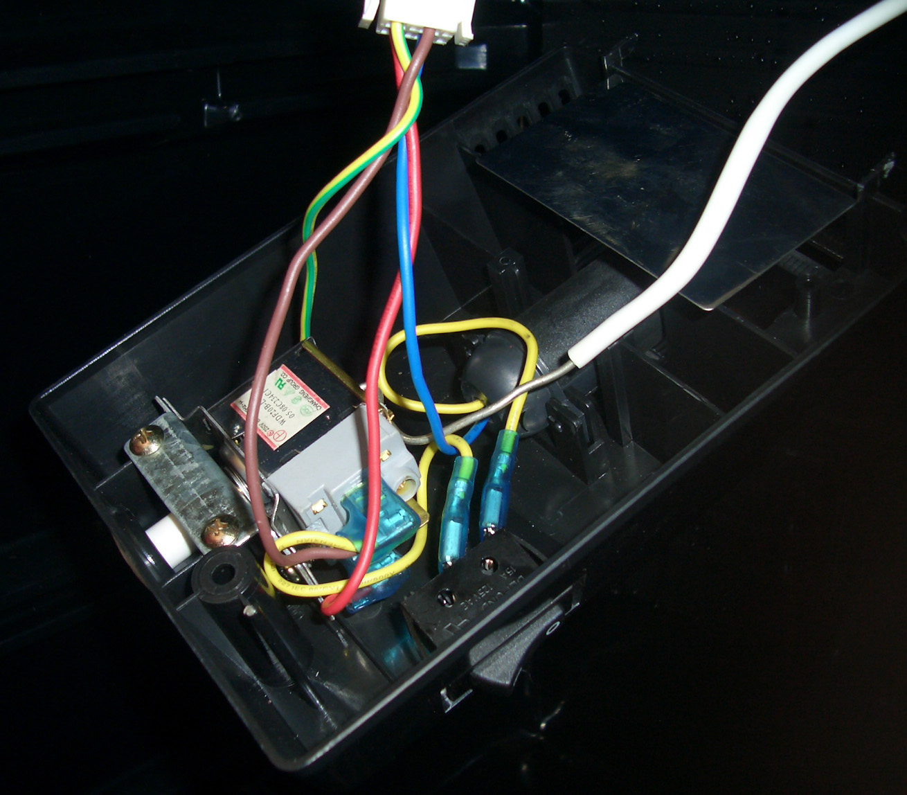
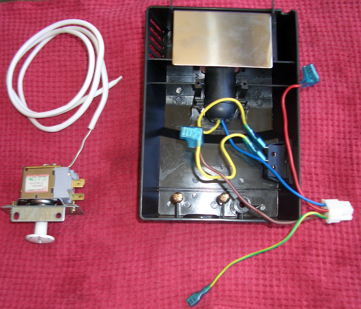
Installation
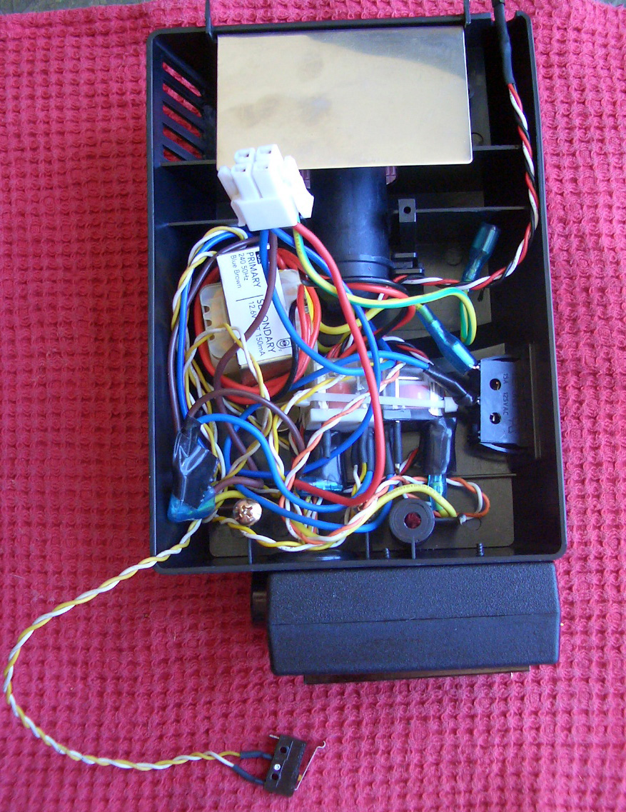
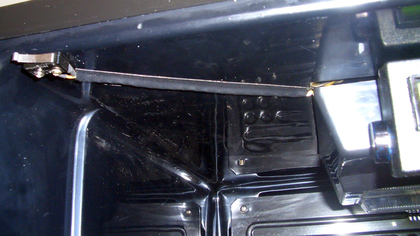
The installation is pretty straight forward. The cooler is still under warranty, so I had to make sure that replacement of the original controller was reversible with minimal damage to the fridge just in case something breaks and I need to get it fixed. This is why the wiring in the photos looks (to say the least) very messy.

![]()
Website hosted by WWW.EazySiteHost.Com |