PCB Fuser
Another useful tool is a device to transfer and fuse laser printed artwork to a blank PCB. I have used the ironing on method for a long time, however it is very messy and inaccurate. A great deal of care needs to be taken to apply the correct amount of heat and pressure to every part of the PCB to achieve a dissent quality transfer. This can leave you with re-doing from scratch few times before you are happy with the outcome. I have tried laminating machines with no success. There are 2 fundamental problems with using laminators to transfer artwork to PCB:
1. The clearing between rollers is too small for a standard PCB to go through. You can damage the Laminator.
2. It has been designed for plastic and doesn't heat the copper PCB enough to successfully bond toner to it.
Once again I am forced to create a device for the job.
Mechanical
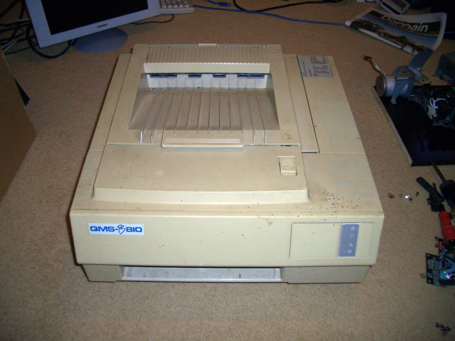
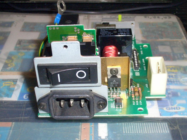
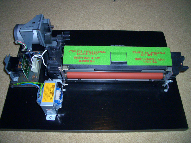
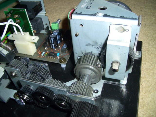
I have chosen to use an existing fuser unit out of an old laser printer. I have removed the fuser unit and the drive train. This particular drive train uses a stepper motor to drive the gears and fuser unit. Steppers are great for this application as they have lots of torque at low speeds.
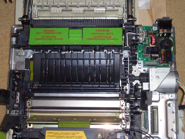
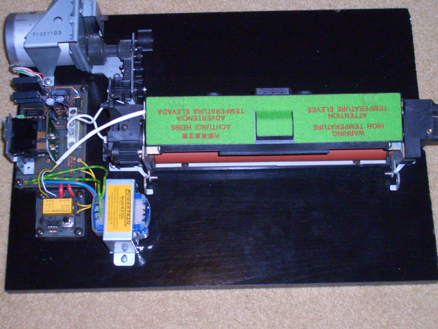
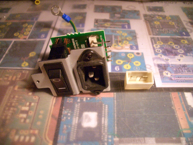
Below are pictures of components removed from PSU.
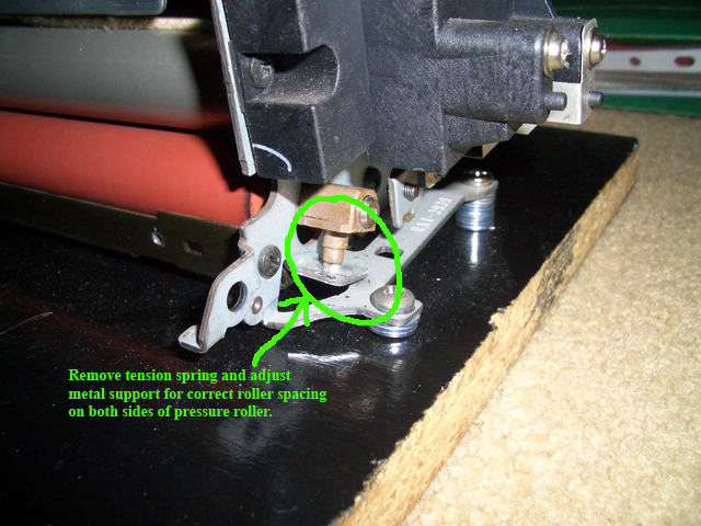
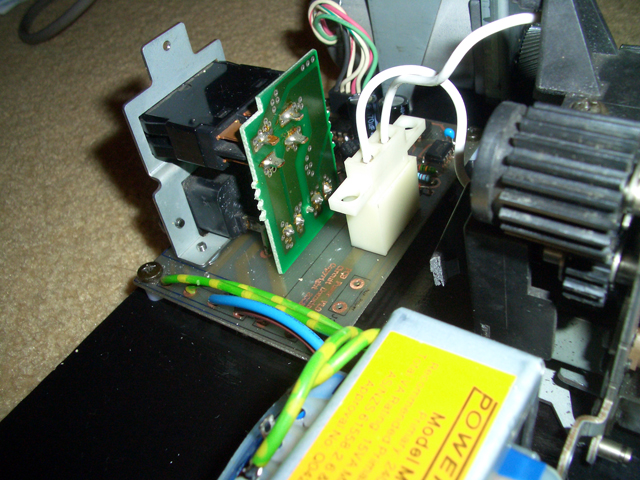
The fuser unit is designed to feed paper so in order to feed PCBs through it we need to adjust the roller spacing as shown on pictures below. The tension spring is not needed as the pressure roller is made of soft rubber and will provide enough pressure for successful transfer.
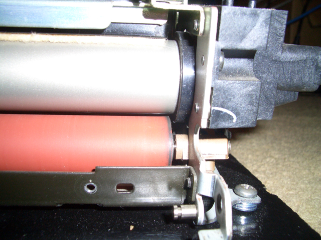
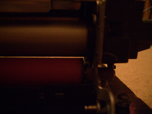
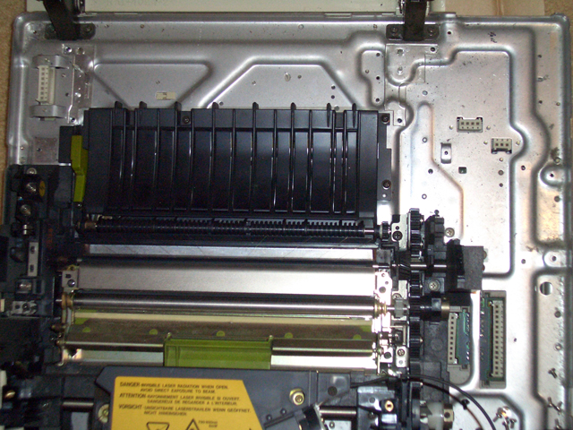
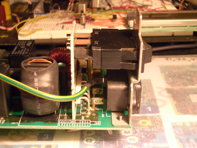
Below are some close up pictures of assembled unit.
Schematic Diagram
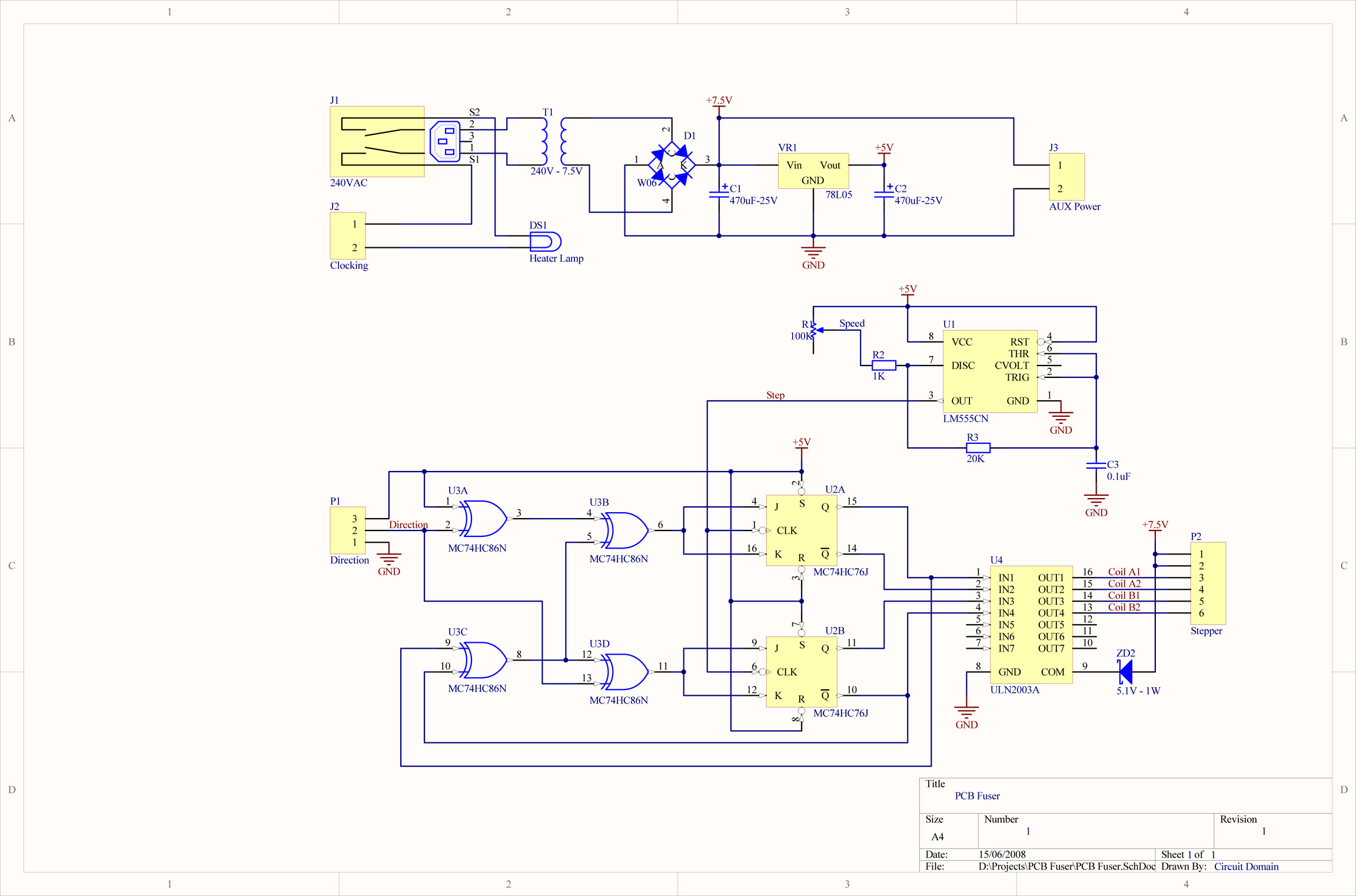
This circuit is as simple as it is clever. It uses couple of JK Flip-Flops and some XOR Gates to generate the correct pattern (1 - 3 - 2 - 4) for driving a stepper motor. Variable clocking is provided by a simple 555 timer circuit, this circuit is not perfect for clocking steppers (it is not 50% modulated) but does the job. The stepper is driven via ULN2003A Darlington array readily available from Jaycar (Cat No. ZK8855).
NOTE: The darlington array chip does get very hot during operation, you will need to provide a heat sink for it.
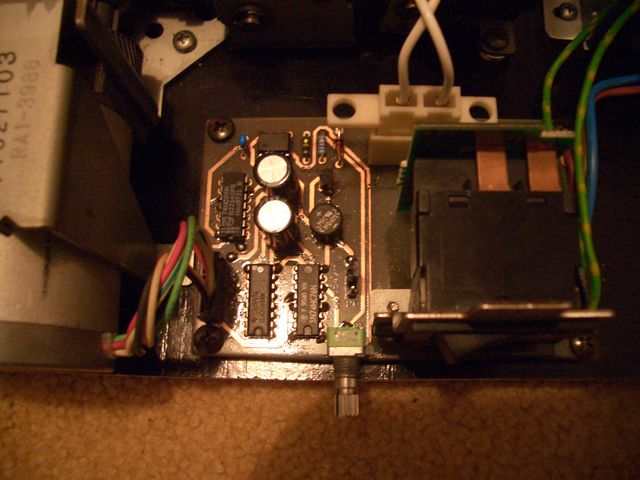
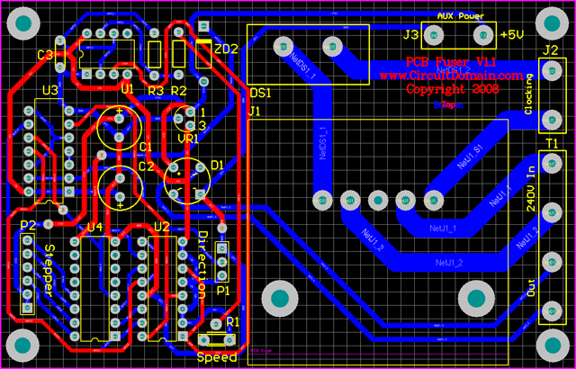
Circuit Board
![]()
The PCB is very simple. J2 and J3 are for future expansion. To manually control fuser temperature using Power switch on the side, J2 should have a link installed. Otherwise you can interface my Universal Temperature Controller to control heater lamp. J3 is an auxiliary +5V output to supply temperature controller. If you just want a simple temperature trigger without an LCD then you can use my Temperature Trigger circuit.
![]()
Website hosted by WWW.EazySiteHost.Com |